Group assignment(Read more about the group assignment.)
Invidual assignment
For the invidual assignment i will make the bipolar stepper driver and the stepperdriver i will use for the steppers for the CNC machine.The board design i downloaded from the output devices week on the fab academy site.
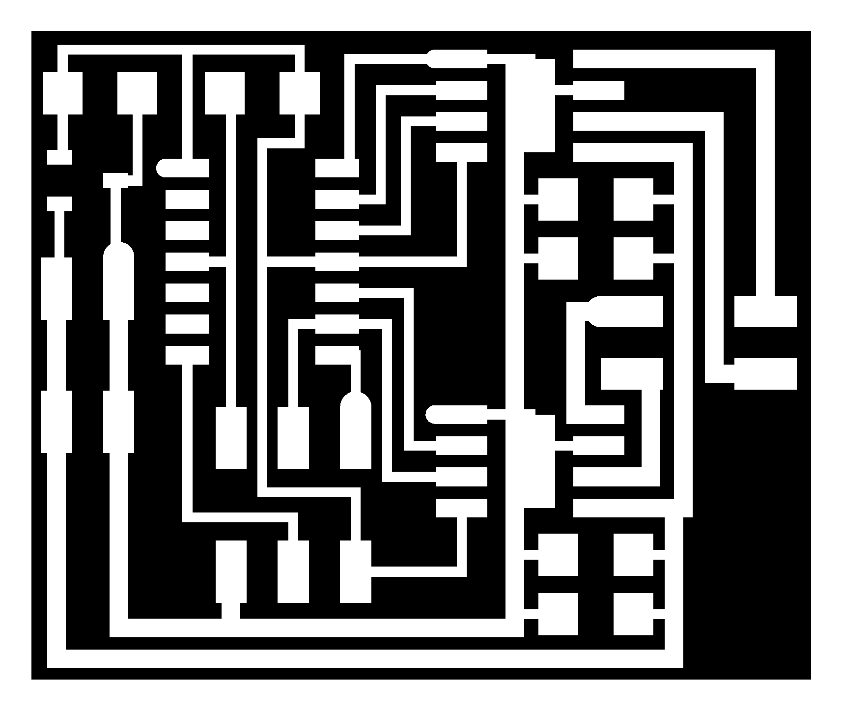
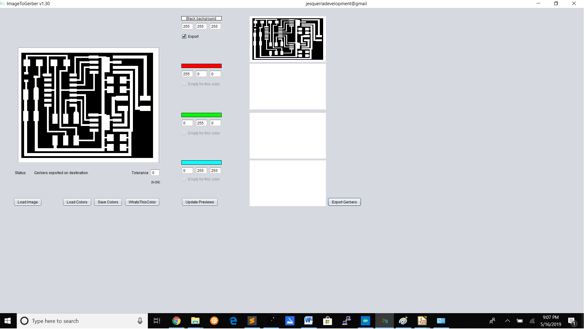
For converting the image to gerber i downloaded the img to gerber coverter.

KiCad redesign
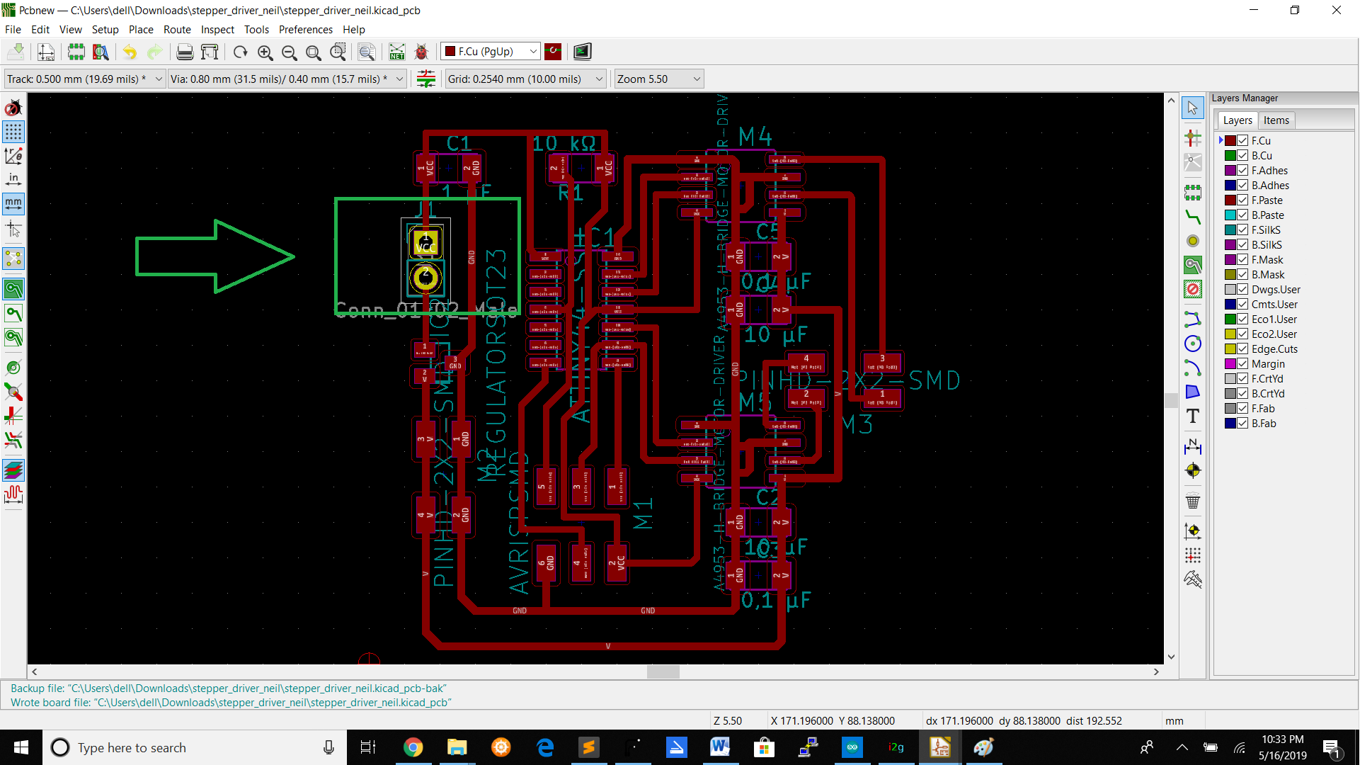
I also redesigned the board in Kicad.
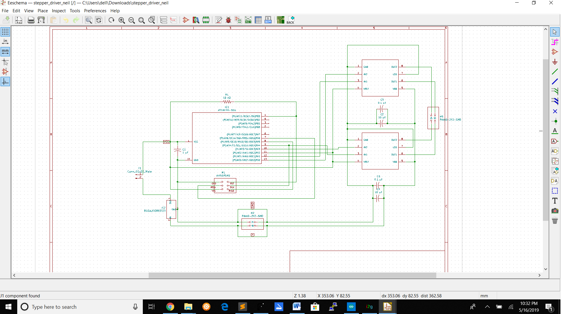
Schematic design of the board
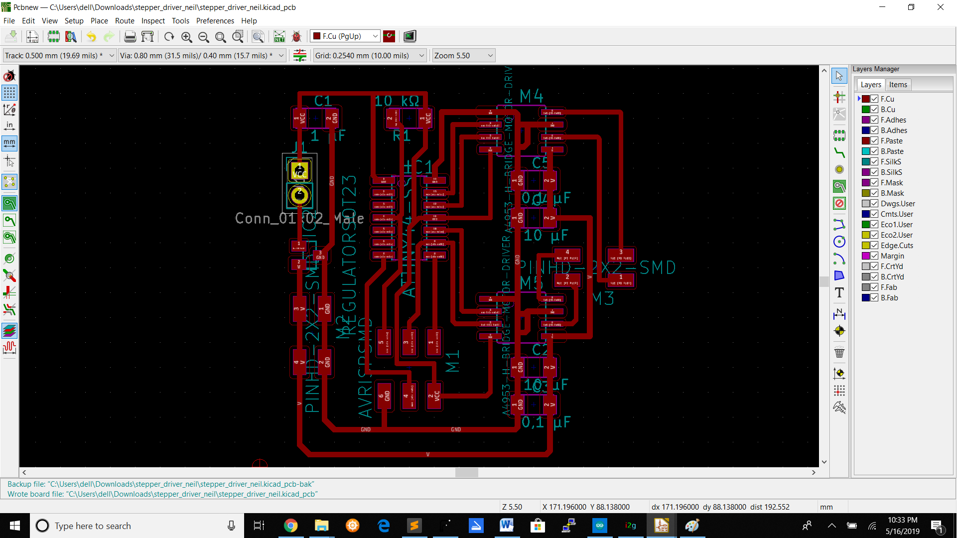
Board design
After redesigning the board i save the file in .gbr format so i can open it in flatcam.
**The reason why i redesigned the board is that when programming the board the linear 5v regulater became hot and everytime when im programming the i had to disolder the regulator.To fix that i added a jumper at the VCC route so that when i'm programming i take of the jumper and after programming connecting the jumper again to give the regulator power again.
After converting the image to gerber or redesigning it,i opened my gerber file in flatcam.
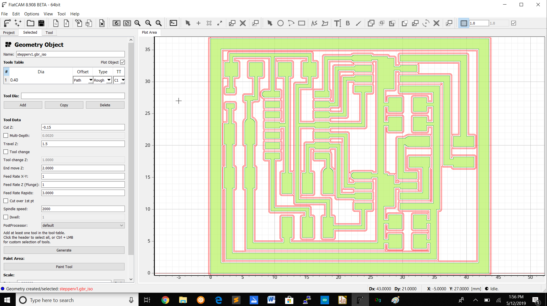
The parameters i used are :
| FlatCAM | Value |
|---|---|
| Tool dia | 0.4 |
| Cut Z | -0.15 |
| Travel Z | 1.5 |
| End move Z | 2.0000 |
| Feed Rate(X,Y) | 1.0000 |
| Feed Rate Z plunge | 1.0000 |
| Feed Rate rapids | 3.0000 |
| Spindle speed | 2000 |
| Cut out | Value |
| Tool dia | 0.9 |
| Cut Z | -1.5 |
| Travel Z | 1.5 |
| Passes | 1 |
| Stepdown | 0.5 |
| Multi depth | Yes |
| Feed Rate | 1 |
| Spindle speed | 2000 |
| Margin | 2 |
After putting the parameters i saved the file as .nc file so i can open it in winpc-nc for milling the board.In winpc-nc you have check the the Z-invert box and also start/end position to zero point.After milling the board i soldered the components on the board.The components i soldered are :
| 2x 2*2 | Pinheader SMD |
| 2 x0.1 uF | Capacitor |
| 1 | AVR ISP |
| 1 | Attiny44 |
| 2x 10uF | Capacitor |
| 1 uF | Capacitor |
| 1 | Linear 5v ic regulator 100mA |
| 2 | A4953 H-bridge motor driver |
| 1*10k | Resistor |
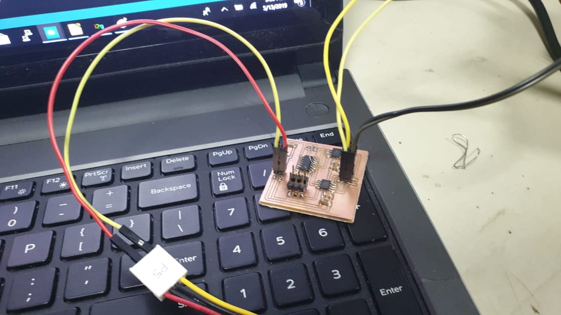
After soldering the components the board looks like this
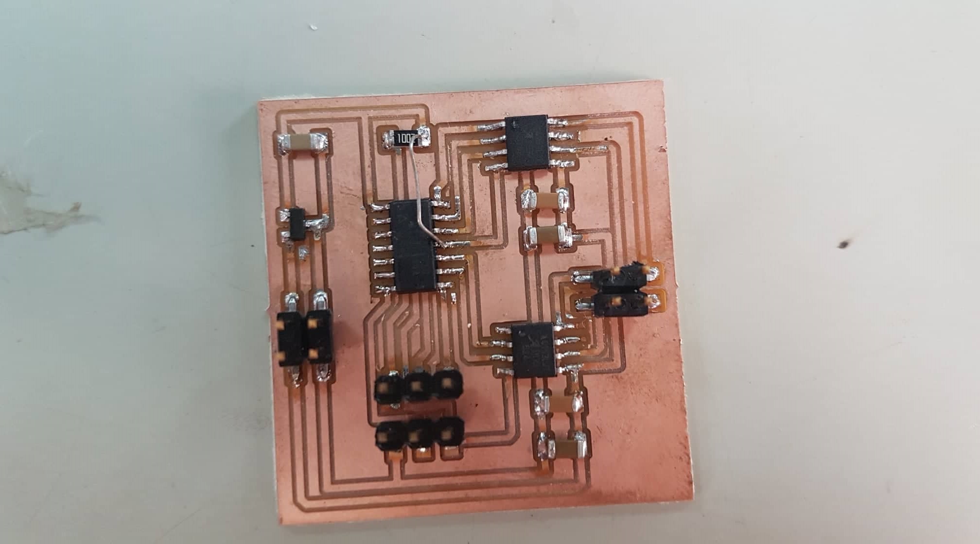
The jumper wire on the board is because i didn't draw the route from the 10k resistor to the Attiny44 pin after by redesigning the board.
Setup,programming and testing
Setup
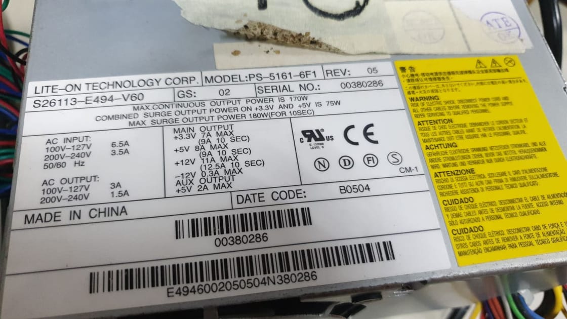
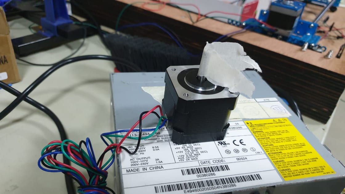
For the setup i used a old pc powersupply to give the stepper power.I used jumper wires to connect the board to the fab isp and also the powersupply.
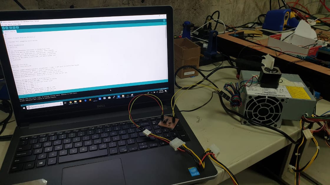
Programming
For programming the board i used the fab isp and arduino ide.
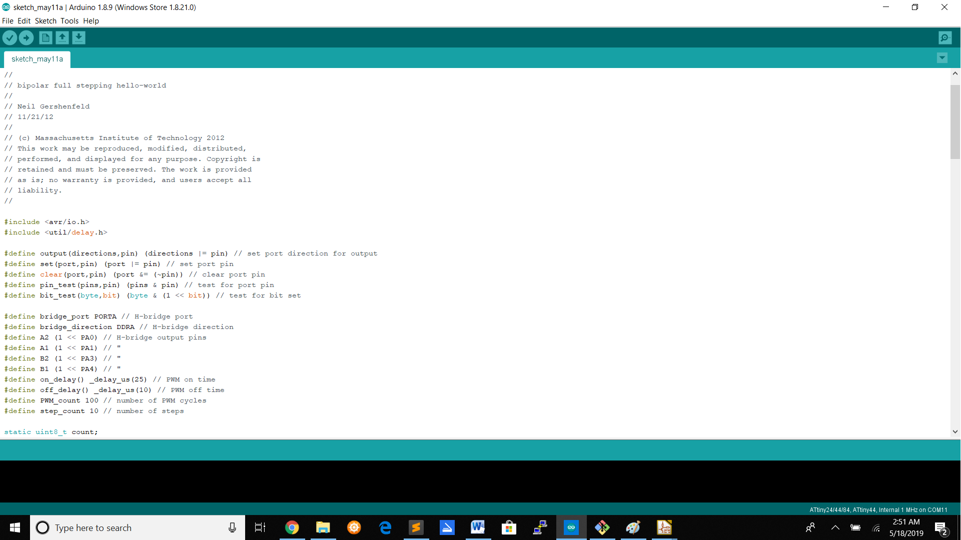
Neil's stepper driver code
Testing the driver
Setting up the driver for the CNC machine
For the CNC machine i programmed the stepper drivers to work serial.The code i used is Neil's code with a intergration with my code.
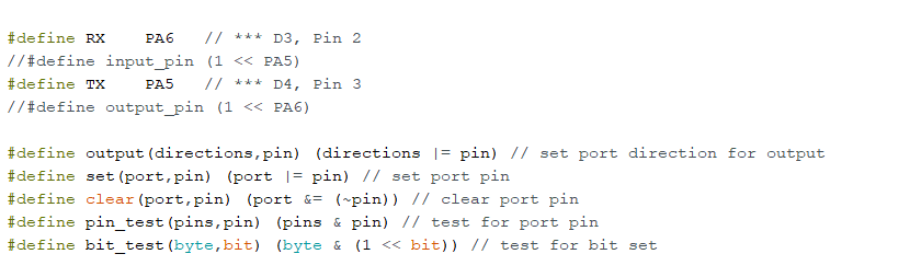
For adding my code in Neal's code i first defined the pins and after that i added a loop for making the stepper motor take action if the number is positive.Then the stepper will turn clockwise but if it negetavive it will turn counter clockwise.For every driver of the axis you are going to use you have to put in the letter that define the axis.For example you have to fill in the X and that will be for the X-axis.
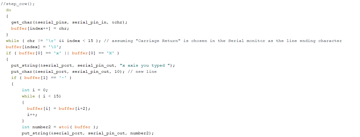
For every axis you got to put another letter
Files
Stepper driver codeSchematic design
Board design
Trace winpc-nc file
Cut Trace winpc-nc file
Stepper driver X-axis code
Stepper driver Y-axis code
Stepper driver Z-axis code